
I was recently contacted by a company to evaluate the strength of a trailer frame design. They received a design from another company – one generally considered reputable – but questioned whether the engineering was adequate.
Is the trailer frame strong enough?
This type of request, to evaluate a design, is not unusual. Clients sometimes ask us to review a trailer frame design to identify weak points or confirm that it will perform as intended. So, after some discussion, and a quote, we accepted the project.
This project is done under a Non-Disclosure Agreement (NDA), so we will not discuss the company, the product purpose, or show the full design. What we can share are some of the engineering lessons that came from evaluating the design. As a case study, the situation provides several valuable things to learn.
Setting The Stage For A Case-Study
It is not our purpose to disparage a vendor design or the designers. We do not know their assumptions or the requirements they were given. We assume the vendor design meets similar specifications as those given to us, because many characteristics of the design suggest that is the case. However, we cannot know for certain.
Please remember that we are presenting only our perspective. We have been designing trailers since the 1990s – so we have seen a few things. Experience is not everything, but it certainly helps when evaluating trailer frame structure.
This situation is ripe for study primarily because of the source of the vendor design. To me, a big reputable company in the trailer manufacturing industry should know. If anyone, they should be a source to trust. Yet, in this case, even the non-engineers who became my customer could tell something was not right. This emphasizes the need to use your senses as you consider a trailer – whatever the source.
For this case study we will dive into what we were given, the specifications we were provided, and a comparison of the trailer frames. We will then compare for trailer strength. To avoid confusion, we will refer to a "vendor design", the "Synthesis design", and an earlier "prototype design" (which we know very little about).
Specifications Defining The Trailer Frame Design
Because of the NDA, we will not get into too much detail with the specifications. The big ones are these:
- Trailer capacity at 21,000 lbs on three 7,000 lbs torsion axles.
- Gooseneck design.
- 40 ft trailer length - with 32 ft main deck.
- Full legal width at 102 inches wide.
- A high percentage of the load will be at the trailer deck perimeter.
- Weights and spacing for items in the trailer were given.
While there is a lot more detail about this a custom trailer - there is no need to get into the details.
Before seeing the analysis results, it is worth asking some simple engineering questions:
- What materials would you use to design a trailer with these specifications?
- Do you see anything in these specifications to give you concern?
Where Are The Concerns?
To discuss concerns, we need to bring in some information I have not yet given you about earlier trailer frame design. Apparently there was an earlier prototype design where the trailer frame failed. I don't know what failed, or anything about materials or loads. The vendor was hired for a new design, which they did.
In reviewing the vendor design, something caused the customer to pause, which lead them to Synthesis. They gave us the vendor design to review. The customer concerns were something about the materials in the vendor trailer frame design.
Per the first question above: What materials would you use?
The vendor design has 8 x 4 x 3/16 inch rectangular steel tube as the main beams, and 2 x 4 x 1/8 inch for the cross members. Outriggers to achieve full width are sheetmetal (not shown). Here is a simplified version of the vendor trailer frame design.
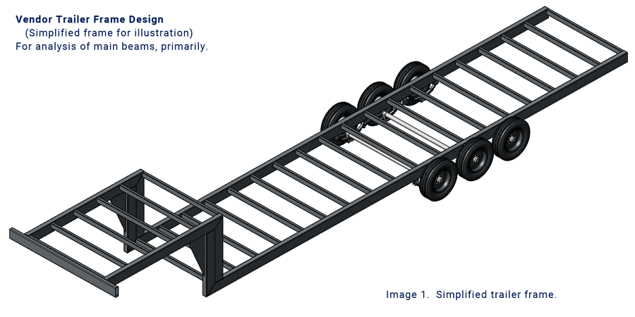
Proprietary items are removed from the trailer frame design for this case study analysis. Additionally, we have simplified it (like removing outriggers) for ease of analysis, and clarity in presentation.
Engineering For Strength
What does the analysis show? Is there anything to support the strength suspicions of the customer?
After applying loads, here is what the computer thinks...
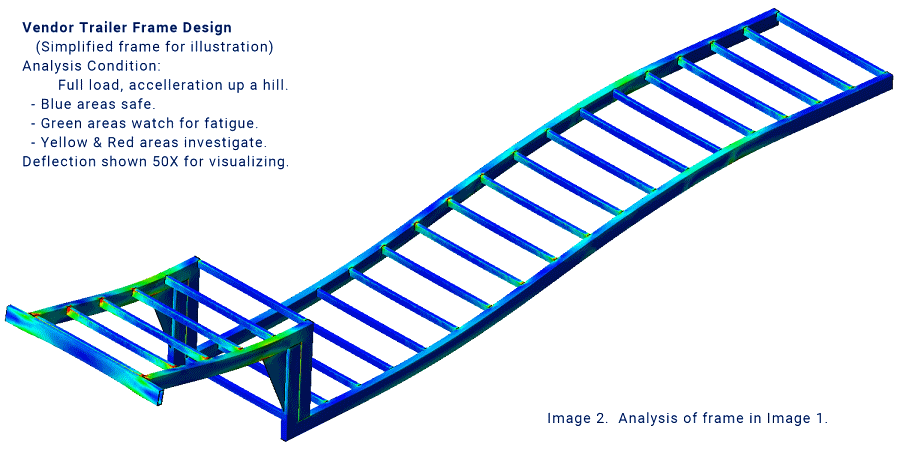
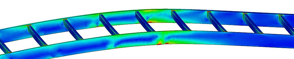
The FEA analysis shows several areas of concern with stress and deflection in the main beams. The structure overall is not horrible. It does have points to examine, especially for beam attachment. If this trailer will ride much on rough roads, the bright green areas are suspect for fatigue under full load, over time.
Analysis does not examine the effect of torsion axles. It uses leaf springs for consistency in the comparison for this case study.
I know, the topic of torsion axles can be controversial - unless you really think about it. They are great for singles, but we DO NOT recommend them in multi-axle applications. Torsions increase frame stress in the area of mounting, even if they all carry an equal load. Yet they do not share loading, so there are times when the trailer frame will experience spikes of even higher stress. Read the full engineering opinion on Torsion axles in Tandem or Triple.
One last key point: Since the trailer carries expensive equipment, a marginal trailer frame design has greater risk. This is one more confirmation of the early customer concerns.
Engineering For Trailer Function
The quote I gave them said I am happy to do the analysis, but I already know an 8 inch beam is insufficient for 21,000 lbs stretched over 40 feet. (I also gave them a quote for a completely new design.)
Additionally, per our question above: Do you see anything in the specifications to give you concern?
The vendor design allows only 8 ft of gooseneck length. While 96 inches may sound fine, 16 inches is consumed by the transition from the main deck to the gooseneck. In addition, the upper deck overhangs the coupler by several inches.
The result is reduced truck turning clearance. In practical terms, some trucks, if towing this trailer, would strike it during tight turns, particularly when backing.
What do you think? Was the customer right to question the vendor design?
How Is The Synthesis Trailer Frame Design Different?
- First, we recalculated the loads and load placements, then concluded that the axles need to move back a little.
- Second, with early calculations we decided on 10 inch I-Beams instead of 8 inch tube.
- Third, we used a better design for the structural transition from the main deck to the gooseneck. (See this article about Engineering for Gooseneck Trailers.)
- Fourth, there are better ways to support perimeter loads, so we integrated concepts from our previous Tiny House Trailers design. (Not shown in these images.)
- Fifth, a quick discussion with the customer gave us allowance to add some inches to give trucks proper turning clearance.
- Sixth, we changed the axles to a leaf spring style to allow load sharing. For ride enhancement, we discussed the Morryde rubber enhanced equalizers. (See above, torsions are contrary to engineering for strength.)
Now for the fun part. Here is what the computer thinks of the Synthesis trailer frame design...
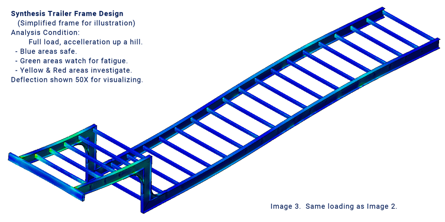
Do you see a difference when comparing to the image above?
This trailer frame design is based on our existing tiny house trailers which are proven very strong and capable. It is a little heavier than the vendor design, but not as much as you might first think.
Finally, a standout from the comparison is frame deflection. Under the same loads, using the same axles, the Synthesis design flexes about half as much. That means with every bump in the road, this trailer will "bounce" half as much. It is a lot stiffer.
Detail On The Main Trailer Beams
As a quick reference, just to show the significance of engineering for strength, stress calculations are based on forms of this equation. σ = My / I
- σ is stress.
- M is the bending moment.
- y is the distance from the neutral plane (for simplicity, the vertical center of the beam).
- I is the area moment of inertia.
Remember, this is a simplified look at trailer frame design, so this example is only for setting the paradigm.
An 8 x 4 x 3/16 inch rectangular steel tube:
- has an area moment of inertia, I, of roughly 35.4 in^4
- for simplicity, has a y of 4 in.
- has a weight of 14.53 lbs per linear foot.
A 10 inch x 19 lbs I-Beam:
- has an area moment of inertia, I, of roughly 94.6 in^4
- for simplicity, has a y of 5 in.
- has a weight of 19 lbs per linear foot.
If we assume the same bending moment for both cases, comparing 4/35.4 to 5/94.6 shows the I-beam is ~2.1 times the bending strength. The penalty is 4.5 lbs per foot more weight. (All generalized numbers for illustration purposes only.)
Another point of interest for this build, according to the steel price quote at the time, because rectangular tube is so expensive, the I-Beam actually cost less than the tube.
So, more than twice the strength, less cost, and only 2% weight penalty. (440 lbs heavier in 21,000 lbs trailer capacity.)
Cross Beams And Outriggers
As noted above, the vendor design has 4 x 2 x 1/8 inch rectangular tube for cross members. That is sufficient for most places on the trailer frame, however, because of some loads, this size is marginal in some places.
The Synthesis design also uses 4 x 2 x 1/8 inch rectangular tube for most cross members, but in areas of higher load, 3/16 inch wall substitutes. Our philosophy uses the right material in the right places - even if it is not traditional thinking.
We can say the same for the outriggers. At Synthesis, we recognize all the extra work that goes into attaching and aligning outriggers. That labor is not trivial, and it is prone to less than perfect alignment. So, the Synthesis design avoids all that, reduces the welding, and uses CNC to assure beautiful clean alignment.
The advanced manufacturing methods save a lot in skilled labor (assembly and welding) time as well as give greater strength. This is something we have proven over and over with our tiny house trailer frame designs.
Completing The Case Study Comparison
The thing to make this trailer frame design case study pertinent is the contrast in performance. As we compare the FEA images above, we note that the trailer frame design is similar for both, but the deflection and stress are very different. The vendor design is not horrible, but it will not perform well for the loading of this project. Yes, there are stress concerns, but most important, there are deflection concerns, which can lead to fatigue concerns.
The Synthesis design is a bit heavier, and a lot stiffer. The stresses are lower, which gives greater stiffness. (Note, most often in trailer engineering, the limits are often in acceptable deflection, rather than excessive stress.)
While there are ways to address the high localized stress of the vendor design, they did not. Their design was sent to build. That is a huge red-flag to me.
The customer later told us about an early prototype that failed. That is what made them suspicious of the trailer frame design received from the vendor. I don't know if it is similar to the design that failed. Either way, they hired the vendor to do better, but as you can see above, it is good they did not build that trailer.
There is a lot more to evaluating and engineering for strength in a trailer frame design, but for this article we are highlighting the main beams and cross members. That is the backbone of the whole trailer. If the main beams are engineered and implemented correctly, the entire trailer structure benefits. If they are not, the outcome is not pretty.
It is worth noting, we have seen several issues of failure from inadequate design. Here is an article with an important one.
Good luck in all your trailer builds. If you need a custom trailer frame design, let us know. We are happy to look at your project and talk about design. Thank you for visiting Synthesis Engineering.
Read here for more about Custom Trailer Engineering and Design.