Have you ever wanted to control a model, perhaps using a relation, but couldn't find the
dimensions needed? Have you ever wanted an assembly to reflect different conditions but couldn't
get the parts to update to the various conditions?
 |
| Figure 1 |
|
Here is a nifty way to get the information you need. For this Tip of the Month, we will use a
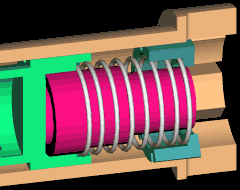
simple assembly with a spring. As the assembly moves, the spring must compress and expand. Figure 1
shows the partial assembly cut-away.
Using a skeleton (or other method) for control, the parts
can "move" with respect to each other (see "Skeletons"
in our August 1998 Tip ).
Now, How can we get the spring to update with the model changes?
A simple way is to put a Reference Dimension in the area of the spring pocket, then write a relation to
make the spring become the length measured by the ref dim.
Model Reference Dimensions (different than Drawing Reference Dimensions) are created using
SET UP > REF DIM > CREATE. There are two dimensioning schemes to use:
BY EDGE which requires a view orientation, and BY SURF. The BY EDGE option allows a
dimension to be created using model edges, but will only appear when the model is in the defined view because
the measurement is relative to the defined view. (Think of it as a 2D projection of the view.
Try an angle dim for something that would not be valid in 3 space.) The BY SURF option allows
dimensions to be created independent of a view point, but must be created between planer surfaces.
 |
| Figure 2 |
|
Going back to our example, we used the BY SURF option then chose the 2 planer surfaces the spring sits
against. The resulting Ref Dim is shown in Figure 2.
To make the spring length update, we simply write a relation equating the spring length to the new
Ref Dim. Note: the ref dim symbol is "rd0"; Use Info > Switch Dims to show the
value. This is the notation Pro/E uses for model Reference Dimensions, so the relation is:
is the name of the dimension defining the
spring length in the part model, and :28 is the notation for the part as used in this assembly.
(See tips from September 1999 and
October 1999 for more information on relations.)
When we change the position of the other models, the ref dim will update, and the spring length will change.
One word of warning: When the model is changed in a way that would
change the spring length, the spring will not update its length as first expected.
Why?
 |
| Figure 3 |
|
Calculation order. First Pro/E evaluates the relations, then regenerates the
model, then evaluates the ref dim. Since the ref dim is dependent on the model changes, the
models must regenerate before the ref dim can be evaluated, but the relation driving the spring length is
evaluated before the model regeneration.
Sound like a viscous circle?
The solution is to regenerate twice. Figure 3 shows a sequence of changing dimensions and the subsequent
double regeneration.
Have fun with this little technique. For more fun with Ref Dims,
try extrapolating these techniques to part models and/or use the REF DIM option in Sketcher.
Try building Sketcher relations using sketched Ref Dims.


