|
Creating Solids from DXF's
If you've ever dealt with importing geometry from another CAD source, you've also dealt with the headaches
of finding the right translation medium. Pro/E does handle several Import/Export types. In our
February 1999 Tip we addressed issues with 3D surface geometry like IGES.
But, What if the information is only available in 2D?
like DXF? How do you get that into a Pro/E solid model?
To start, notice that Pro/E will not import 2D formats directly into a 3D model, so we have to use a work around.
The work around follows these steps (more detail in the example below):
- Import the DXF file into a blank Pro/E drawing.
- Align the respective views for export.
- Export views as IGES (so they can be read in 3D).
- Import the views into the Pro/E model.
- Build the part geometry in 3D based on the 2D info.
The above steps are illustrated in the following step by step example
showing how a DXF file was used as reference to create a Pro/Engineer solid.
1. Start a blank Pro/Engineer drawing. File > New
> Drawing > give it a name > OK > make sure the "Optional Default Model"
field is blank > OK.
2. Import the DXF file. File > Import >
Append to Model > choose DXF or All Files from the "Type"
pull down menu > select the correct DXF file > OK.
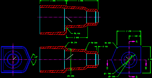 |
| Figure 1 - Views of DXF file |
Note: If Pro/E complains about the scale, it is possible that the DXF was created
in a different units scheme (Metric vs. English) or the format you chose is too large or small. Usually, you want to
preserve the original scale. That may make the new drawing entities either very large or very small with respect to the
Pro/E drawing border, but this blank drawing will eventually be discarded anyway, so zoom as needed to see it.
 |
| Figure 2 |
|
3. Locate the 0,0 point on each view. Once the drawing appears,
use the >Sketch and >Tools menus to sketch a line with one vertex at the point in each view where you
would like the coordinate system (0,0,0) to be in the new (yet to be created) Pro/E part.
Note: For many models step 3 will not be necessary,
but if you need the coordinate system to be at a certain spot in the final model, you must identify that point here.
Figure 2 shows a white diagonal line sketched with one vertex at the center of the circle. The line was created by
first sketching a line horizontal using the vertex (end point) of the imported horizontal line then picking the vertex of the
vertical imported crossing line. The first line was deleted after the diagonal line was sketched.
4. Move the drawing view (or a copy of it) to the lower left corner of the drawing to
prepare to export to the Pro/E part model. When the drawing is exported, Pro/E uses the lower left corner of the drawing
as the X0Y0, so the drawing view to be exported must be set-up for this (0,0).
Note: Either Tools > Copy or Tools >
Translate will work with slightly different prompts. I like Copy because it makes
steps 5 & 12 easier.
To copy the view, use Detail > Tools > Copy > Translate >
Pick Many > select all the desired entities of the view > Done Sel > From - To >
Vertex > select the vertex at the (0,0) point for the view (this may be the end of the sketched entity of
step 3). Next select Abs Coords > Enter 0 (zero) for the
X Coordinate > Enter 0 (zero) for the Y Coordinate > Enter 1 (one) for
the number of copies. The view is then copied to the lower left corner of the drawing. Portions of the view may be outside
the Pro/E border -- that's OK.
5. Use Layers
to show only the desired entities of the single view to be exported.
6. Export the drawing entities in a compatible-for-3D format by using
File > Export > Model > IGES > define a name.
7. Switch windows to your Pro/E part (or start a new part).
8. Create a new coordinate system at the same location of the default coordinate
system (or some offset) using Feature > Create > Datum > Coord Sys >
Offset. The new one is created to give flexibility in rotating or moving the imported view.
9. Import the 2D drawing view using File > Import >
Append to Model > select the file created in step 6 above, then place it using the
coordinate system of step 8.
10. If the orientation of the new import feature is not correct, move it by
redefining the coordinate system of step 8. The coordinate system may be rotated
and/or translated as required.
 |
| Figure 3 |
|
11. To remove entities from the imported feature (like the
drawing border), use Feature > Redefine > select the import feature > Heal Geometry
> Delete. Use the appropriate menu options there to remove unnecessary pieces of the imported geometry.
Warning - these actions cannot be undone so be careful. Figure 3
show the first section imported, drawing border removed.
12. Repeat steps 4 through 11 to import and position all the
desired views. Move the views as appropriate to begin modeling.
13. Figure 4 shows the completed model for our example. In the picture,
the model is shown transparent with the sections and end views all imported and located as applicable for model. The
imported views were used as reference and as visual location as the model was created.
 |
| Figure 4 - Completed part with Imported geometry shown. |
Note: There are times when the imported geometry does not make sense in 3D.
Be prepared to create things (like rounds especially) in a manner consistent with good modeling practices.
Note: The green dim lines shown could also be deleted from the imported views,
but were left as an easy reference to the dimensioning scheme of the original.
Special Thanks to those who asked the question. We hope this gives you a good start. Remember, things are not as
easy as they seem ... sometimes you have to be creative.
See you next month.
|